The build video above covers the build process better than I can ever do in text so you should watch it at least once before building this. The purpose of this post is to provide a list of steps that you can review as you go as well as some background on why I do some things the way I do.
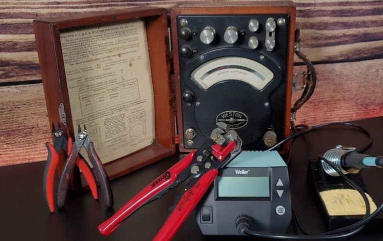
Test, Test, & Test Some More!
When building a project I find it is critical to validate my work after each step. A good example is the testing I did on this project. If you watch the videos you will see there were several stops along the way to verify things
- We started with a bench test to make sure everything worked as expected
- Output Voltages were tested on the internal wiring after installation in the case
- Voltages were checked on the front connectors after they were added
- When making cables, an aviation connector is soldered to one end then voltages are checked before adding the computers power connector
- Finally the voltages on the computer connectors are checked before they are finally considered ready to use
This may seem like overkill but I have found that checking things as I go takes very little time, but troubleshooting an error that was made several steps back can take a long time to find and fix.
Build Order
When you build the power supply I recommend that you do it in this order once you have all the parts needed on hand:
- Bench test everything to make sure it all works
- Cut or 3D print your front and back panels
- Install parts into the front and back panels
- Drill Chassis and test fit all parts (AC and DC Power Supplies)
- Wire the AC Transformer
- Add wires to the DC power supply
- Connect the mains power inlet wires (DON’T PLUG IT IN YET)
- Install into the case then install the back cover
- Test the voltages on the chassis wires before connecting to front panel
- Yes, Now you can double check everything then plug it in and turn it on
- Be VERY careful not to short any wires while testing
- Wire the front panel connectors and meters
- Test voltages on the front connectors
- Make the patch cables that you need and check voltages on each as you go.
- Use to fix lots of retro goodies
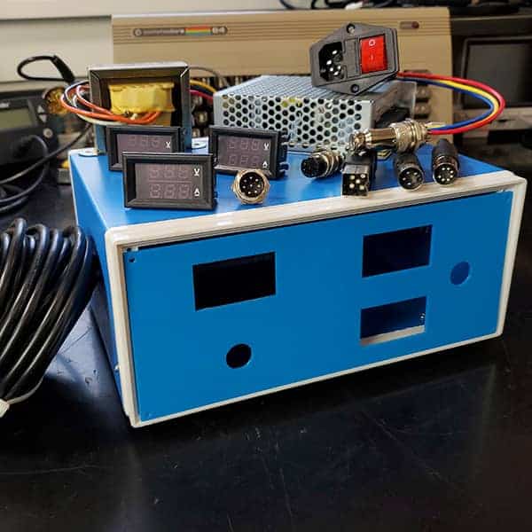
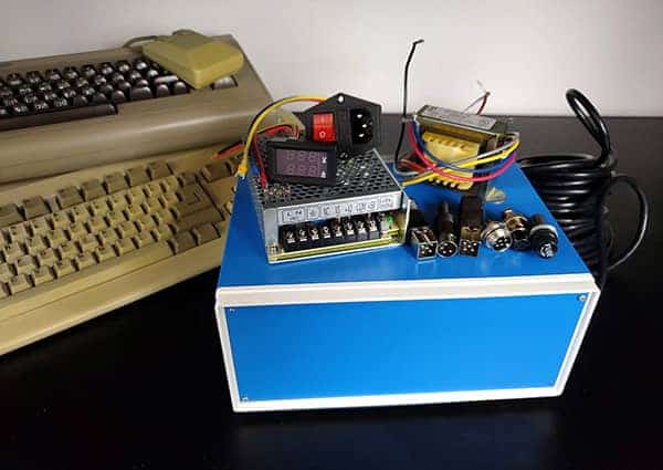
Bench Testing

This is where you make sure you understand how everything goes together and that all your parts are correct and working. Temporarily connect everything up, making sure that you are careful with any exposed line voltage. In this case I used some wires with fork connectors to connect to the DC power supply and then connected the meter using clip leads so that there was no need to handle any wires while the circuit was energized. Check that all the output voltages are correct then you can move on.
Front & Back Panels

You have several choices for the front and back panels:
- Cut them from the steel panels provided with the case
- Cut them from plastic sheet material such as textured ABS
- 3D print them with the provided .stls
If you choose to cut the panels then you can refer to the drawings on this post. I would recommend using a nibbler once the bulk of the needed material has been removed.
My preferred method is to use a 3D printer. My panels were printed on a Prusa i3 MK3S+ with a textured bed. The panels were designed and printed by Tom Ebling and the stl files are available on Thingiverse as are the diagrams with dimensions for manual cutting.
Posts in this Series
Part 1 – Commodore Universal Bench Power Supply – Planning
Part 2 –Commodore Universal Bench Power Supply – Parts
Part 3 – This Post
Part 4 – Commodore Universal Bench Power Supply – Making Cables