Now that the requirements have been determined, and a prototype design is complete, it’s time to source the parts to build this Universal Commodore Bench Power Supply. I wasted a lot of time (and money) sourcing parts that I ended up not using. This post will explain what I decided to use and why.
Item links in this blog post will often take you to a choice page where you can choose where you want to source the part from.
Power Supply and Transformer
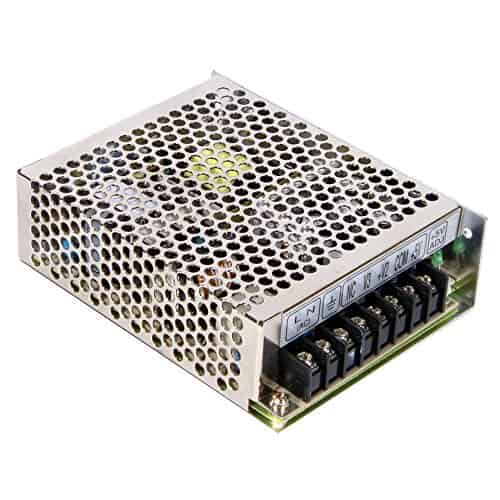
The DC power supply I selected is the Mean Well RT-65B. It provides sufficient power for a worst case scenario (A mod loaded Amiga 1200). It is reasonably priced and Mean Well supplies have been reliable for me. An alternate would be the Mean Well PT-65B which lacks the metal enclosure and has a Molex Connector. Its the same supply but I prefer the safety of the shield and the convenience of the screw terminals when building a prototype. If you prefer the PT-65b for the $5 savings it is here
As I mentioned in the last post I had a hard time finding a 3 Amp, 9V AC power transformer. There is one option that someone pointed out at Digi-Key. It comes with instructions for wiring to 110V or 220V so be careful. You can also elect to skip the 3A that is only needed for early Type A and B Vic-20s. In that case you can use a 1 Amp or higher wall wart which I routinely find at thrift stores, garage sales and the like. They usually cost $1 or less and seem really common, at least in our area.
Connectors
Most of these connectors I recommend getting from Jeff Birts’ Soigeneris. He has high quality and hard to find connectors for several Commodore machines. For many of these I will only have links to one source since they are the only ones I know of. If you have a suggestion then please let me know with the contact page on YouTube. Of course, if you have a dead power supply on hand for these machines then the power cable can be salvaged.
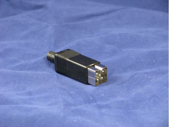
You will need two of these square types since the Commodore 128 and Amiga 500/600/1200 use the same one but are not voltage compatible. BE WARNED you will need to make sure your cables are well marked. Using the incorrect power cable can damage a machine. Later in the build phase I will offer some options on how to make them distinctive!
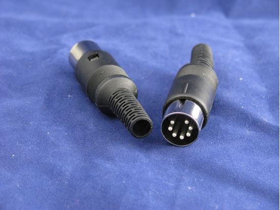
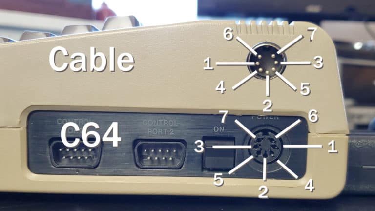
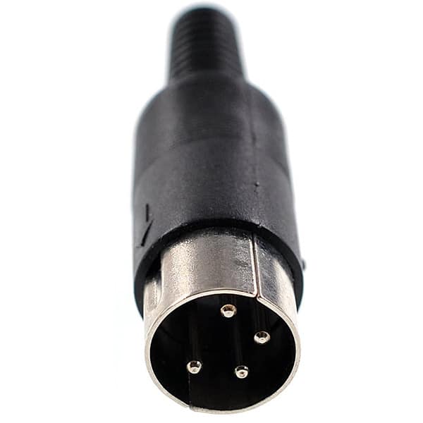
You should only need one of the DIN 7 power connectors for the Commodore 64 and later model VIC-20s. They both use the same connector and voltages. These can also be found on Amazon if you cannot order from Soigeneris for some reason but the ones on Amazon are very cheaply made and difficult to solder without melting the plastic.
A single 4-Pin DIN connector is needed for the external disk drives like a 1541-II. Unfortunately Soigeneris did not have one and the Amazon ones were all I could find. At least they have a better solder cup than the others and come in a multi-pack in case you have issues soldering them.

For connecting the power cable pigtails to the power supply I wanted something attractive and sturdy. I considered a lot of options, and spent way too much ordering connectors to try, including Commodore Style DINs, Molex and aviation connectors. In the end I settled on these because they have a quality feel and appearance yet they are very reasonably priced.
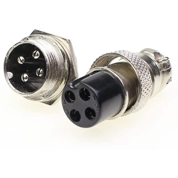
I am using a different connector for the external disk drive power. If I used the same connector for both, then you could connect the wrong cables and possibly cause damage to the computer or draw more current than the supply can provide. A 4-conductor one is fine since all the drives use the exact same 5V & 12V DC voltages.
You might also consider going with a 5-pin connector. That would allow the seperation of the ground and common lines which is an improvement I am considering for a future update.
Enclosure
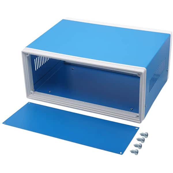
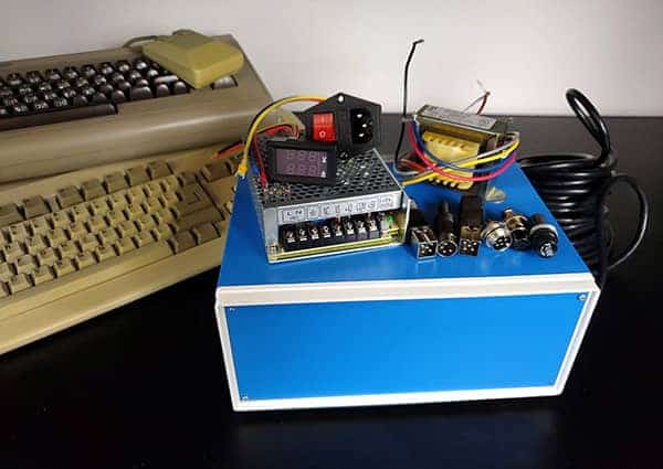
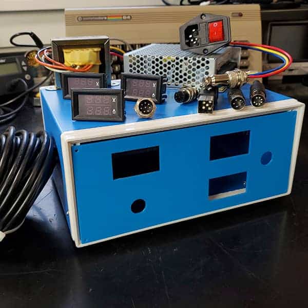
I checked out a few enclosures but, in the end, this was a clear winner. It should be large enough to hold everything, has a large enough front panel for the meters and that blue screams Commodore to me. The only drawback I see is that the included metal panels are not electrically connected to the metal frame so if you decide to use them you will want to make sure they are grounded. I will be using plastic panels so that should not be an issue. The use of only 4 tiny screws in the corners has proven to be a bit of a pain (The panel must be held when unplugging a tight connector). I am looking at options for a small 3d printed brace that would connect the front and rear panels as a reinforcement.
Front and Back Panels

There are several options for the front and back panels. You can cut them from the steel panels included with the enclosure, cut them from plastic, or 3D print them. I am using 3D printed ones that were designed and provided by a good friend.
Edit: An older revision is pictured. The new design has a different layout and only 2 meters. See the next blog post on building the PSU, for more information and links to the .stls
Odds and Ends
Volt Meters
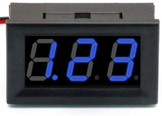
Initially I planned to use a combo volt-amp meter on this project but they turned out to have some severe limitations. Instead I settled on a pair of these volt meters that have a very nice blue color and, in my initial tests, seem very accurate! They also come in red if you prefer. Only 2 are needed but they come is a set of 6. Because these are powered by the voltage being measured the 5V meter is a lot dimmer than the 12V one. I may upgrade to meters with a separate power input as a result but these function fine as is.
Power Connector with Switch and Fuse

This is one item you may have to do a little research on. The one I have here is for 110/220 and uses a standard computer power cord so it should work for most countries. Be aware that this uses non-standard wire colors if you are in the USA so be sure to check. In this case the Blue wire is Hot (Would be Red in the USA) and the Red wire is Neutral (Would be white in the USA). I will be reversing the wires in my build so that red is Hot!
This includes a 5 Amp fuse so you may find you need to upgrade to a slightly larger one if you are pushing things to the limit (6-8 Amps at most, no larger)
You will also need some 5-conductor power cable (This is 20 AWG) for making the pigtails. I bought this off of Amazon just for the simplicity (And I had a gift card, every penny counts these days). DigiKey seemed to want to sell me 100′ or more! You can get this wherever you like, just be sure it is multi-stranded 22AWG or heavier (20 AWG seems to be the sweet spot) with at least 5-conductors. I would have preferred 18AWG but it was too thick for the DIN connector hoods without shaving them down. You will need a total cable diameter of 6.5mm or less to fit.
Optional Bits
If you want to be able to connect a drive with an internal power supply (Like a 1541) without using an additional outlet, you can use a Y-Splitter cable to connect it.
If you decide to go with the wall wart option for 9V AC, I recommend a very short extension cable for wiring it internally to the AC supply. You just cut off the male end and wire it directly to the internal AC. Be sure not to reverse the hot and neutral wire.
- Heat shrink tubing: https://geni.us/RWRT_HeatShrinkTube
- Crimp fork terminals: https://geni.us/RWRT_CrimpForkCon
- Crimp Spade connectors: https://geni.us/RWRT_CrimpSpadeCon
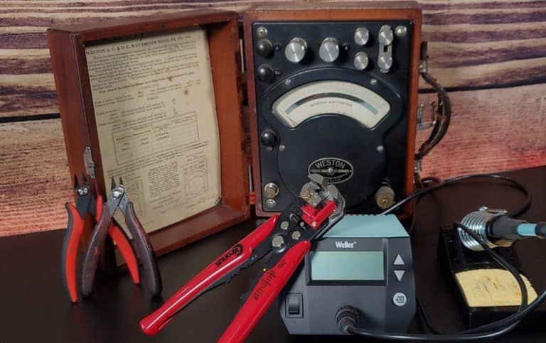
- Wire stripper and crimp tool: https://geni.us/RWRT_StripCrimpTool
See it in Action
Affiliate Links and my Philosophy on Them
Some of these links are affiliate links but many are not. My recommendation, if you are ordering these items, is to use whatever source you are most comfortable with. My preference is DigiKey (Which does not have an affiliate program) but many of the items for this project I purchased off Amazon because they are difficult to find or unavailable at DigiKey. Some items were just a LOT less expensive on Amazon as well. I suspect you might find them on Bang Good or Allie Express but my experiences there have been less than stellar, so I did not include them in my research. Other suppliers, such as Mouser, are great choices as well.
DO NOT buy the connectors on Amazon if you can avoid it. The ones available on Soigeneris are vastly superior!
Posts in this Series
Part 1 – Commodore Universal Bench Power Supply – Planning
Part 2 – <– You are Here!
Part 3 – Commodore Universal Bench Power Supply – Building
Part 4 – Commodore Universal Bench Power Supply – Making Cables