The video is in production but I wanted to get the information for pin assignments out ASAP. I will be adding to this post as more information is available
Common Pin Assignment Confusion
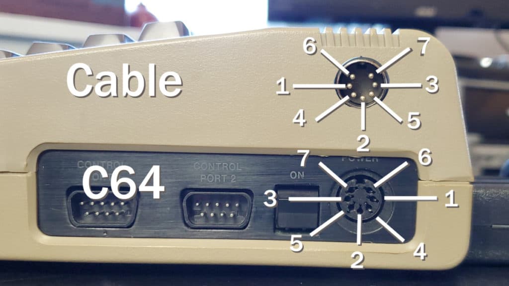
When making cables, for the bench power supply or otherwise, there are a couple things you need to keep in mind. The one thing I see trip people up again and again is that the pin numbers are mirrored depending on whether you are viewing the end of the cable or the port it plugs into (This is because the cable is turned around when viewing the pins). This is often exacerbated when a pin diagram does not state which view it is for. A great example is the Amiga 500 schematics that show the power cable view on a circuit diagram where the board connector goes (Its even labeled CN8)

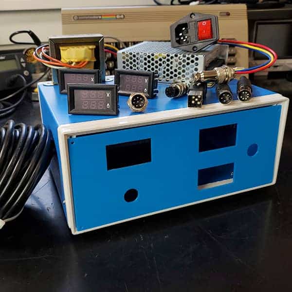
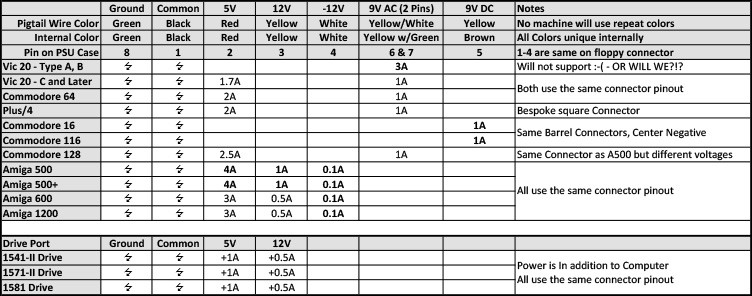
Pin Assignments for the Bench Power Supply
I have selected to assign pin numbers that match the aviation connectors I used in my build. I suspect that most will be marked similarly but make sure they match what I have done.


Posts in this Series
Part 1 – Commodore Universal Bench Power Supply – Planning
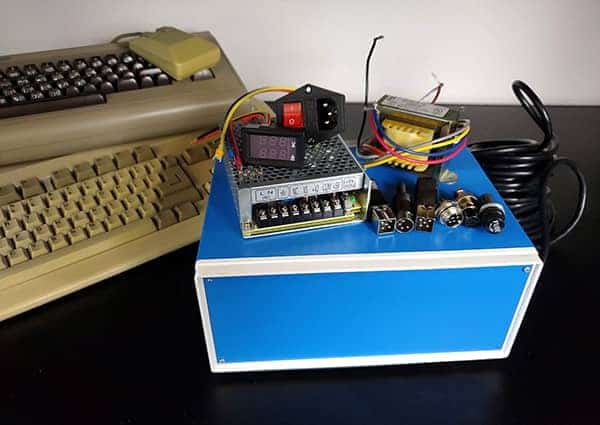
Part 2 – Commodore Universal Bench Power Supply – Parts
Part 3 – Commodore Universal Bench Power Supply – Build
Part 4 – This Post